|
AMSTRAD CPC ON A TV (RGB SCART) The televisions screens are becoming larger and the cpc monitor looks like a old toy by his side. To enjoy our cpc on a large screen we will build a cable to connect the cpc to a TV by euroconnector (scart). |
| A bit of theory |
|---|
|
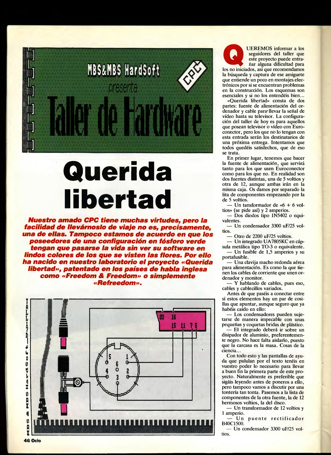
There are plenty of tutorials on the Internet on this subject (certainly better than this), but the vast majority are limited to manufacture a single cable, with five signals (red, green, blue, synchronism and ground), this type of cable works in many televisions but is incomplete and fails in many cases, as there are to put some voltage on the pin 16 of euroconnector to indicate that the television signal that we are giving is RGB. In this simple tutorial we will produce a complete cable, with RGB signals, voltage to switch the TV to RGB and also stereo audio in the euroconnector. This document is based in an article that was published in Amstrad Sinclair Ocio (and who used Joseman in his web), but changing the adjustable resistance to one of 180 and also add audio to the cable.
|
| Required materials |
|---|
| A big TV (CRT, LCD, Plasma or whatever) |
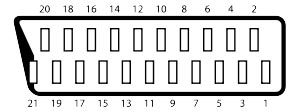
| SCART Cable (Euroconnector) |
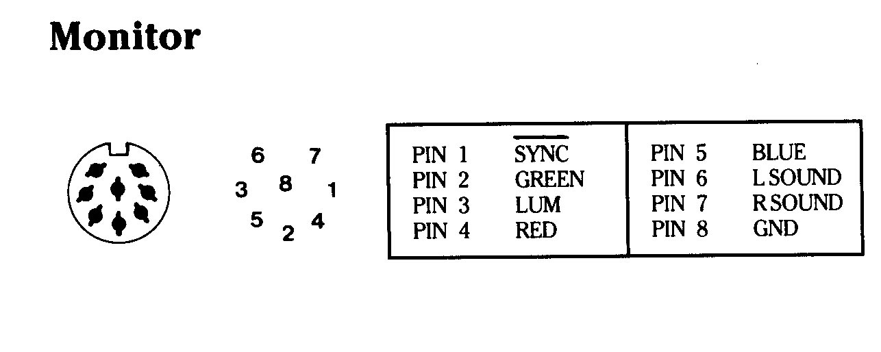
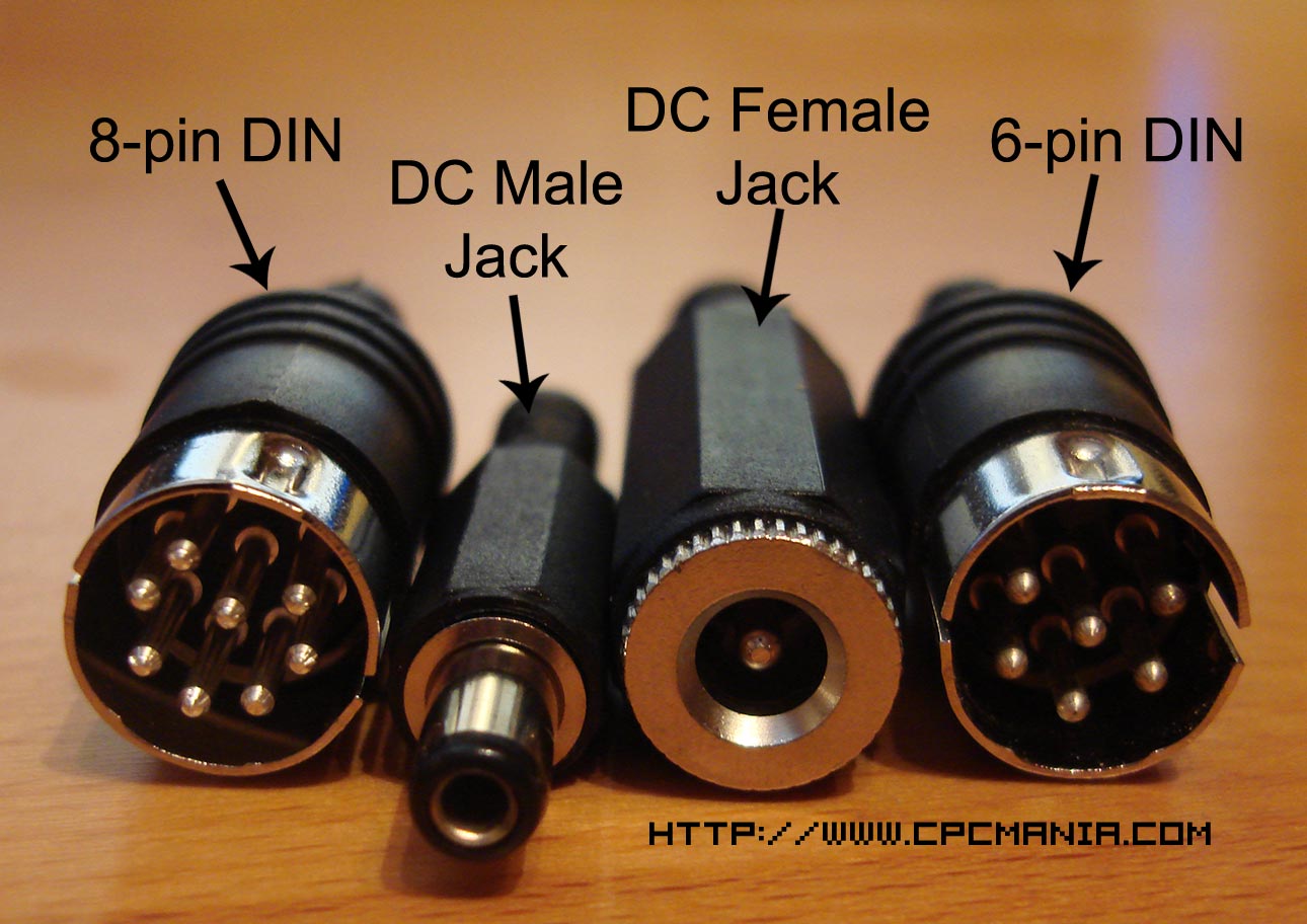
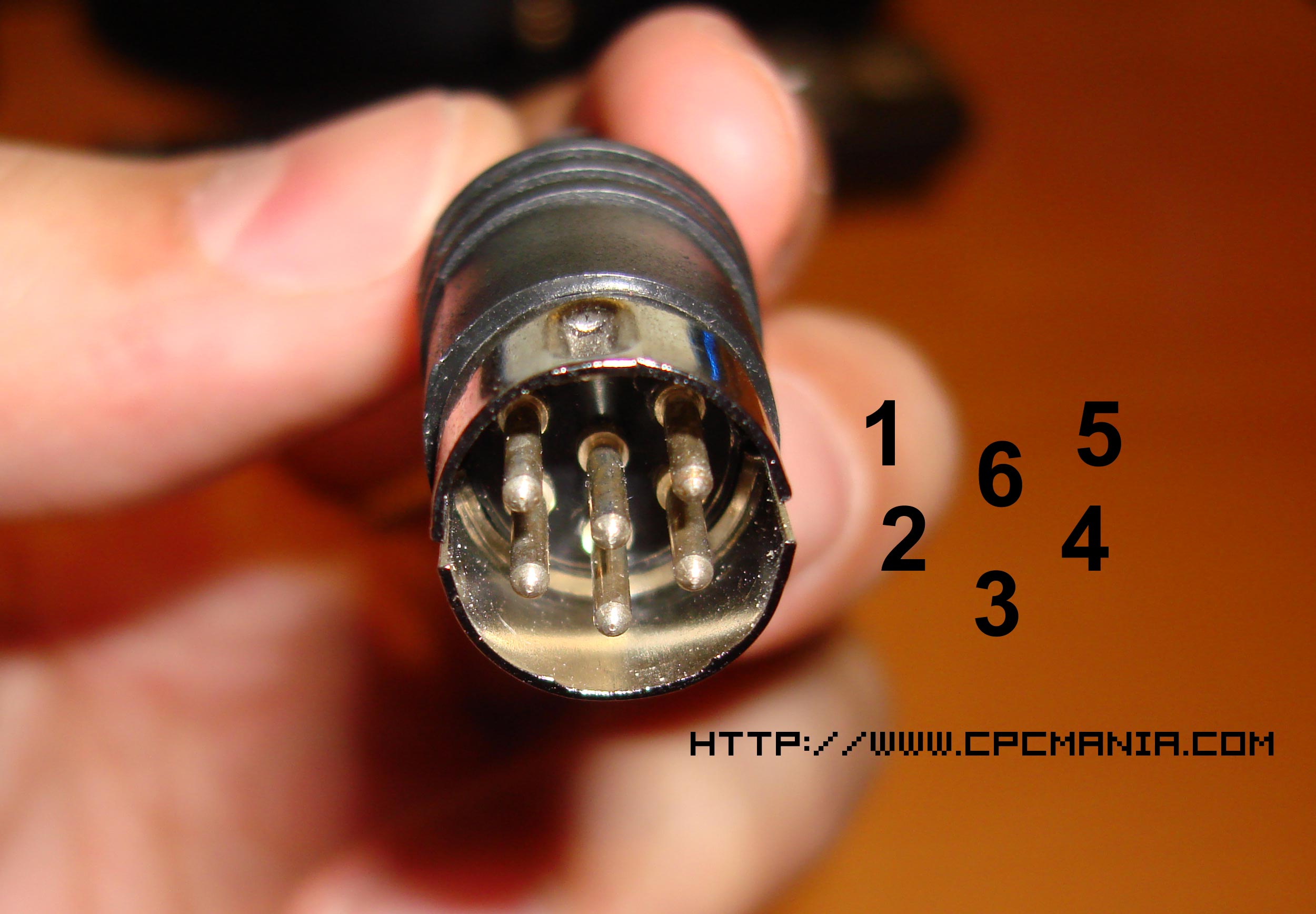
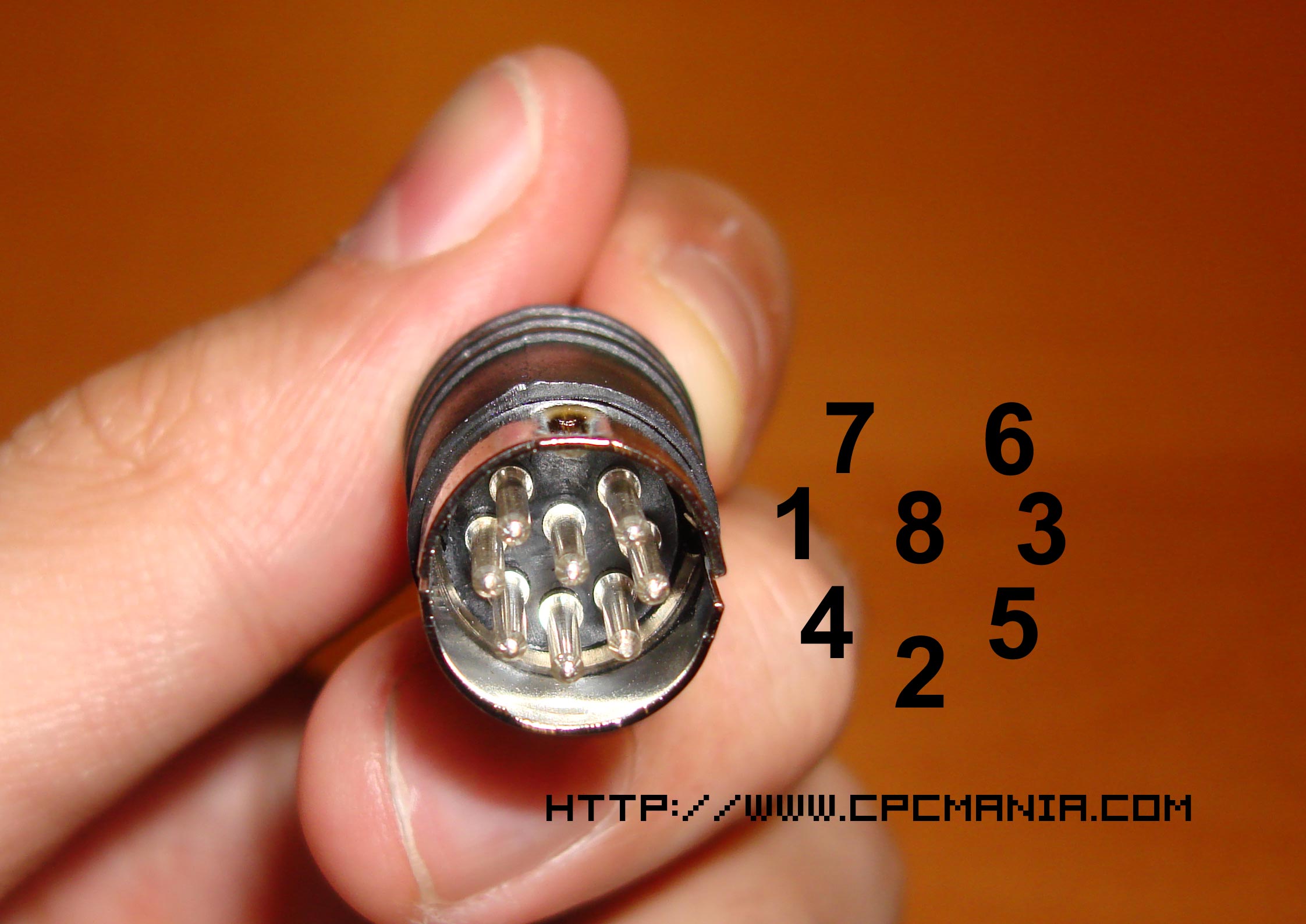
| 6-pin DIN male plug (8-pin for the cpc plus range) |
| 3.5mm stereo male plug (not necessary for cpc plus) |
| DC Male Jack (2.1x9mm) |
| DC Female Jack (2.1x9mm) |
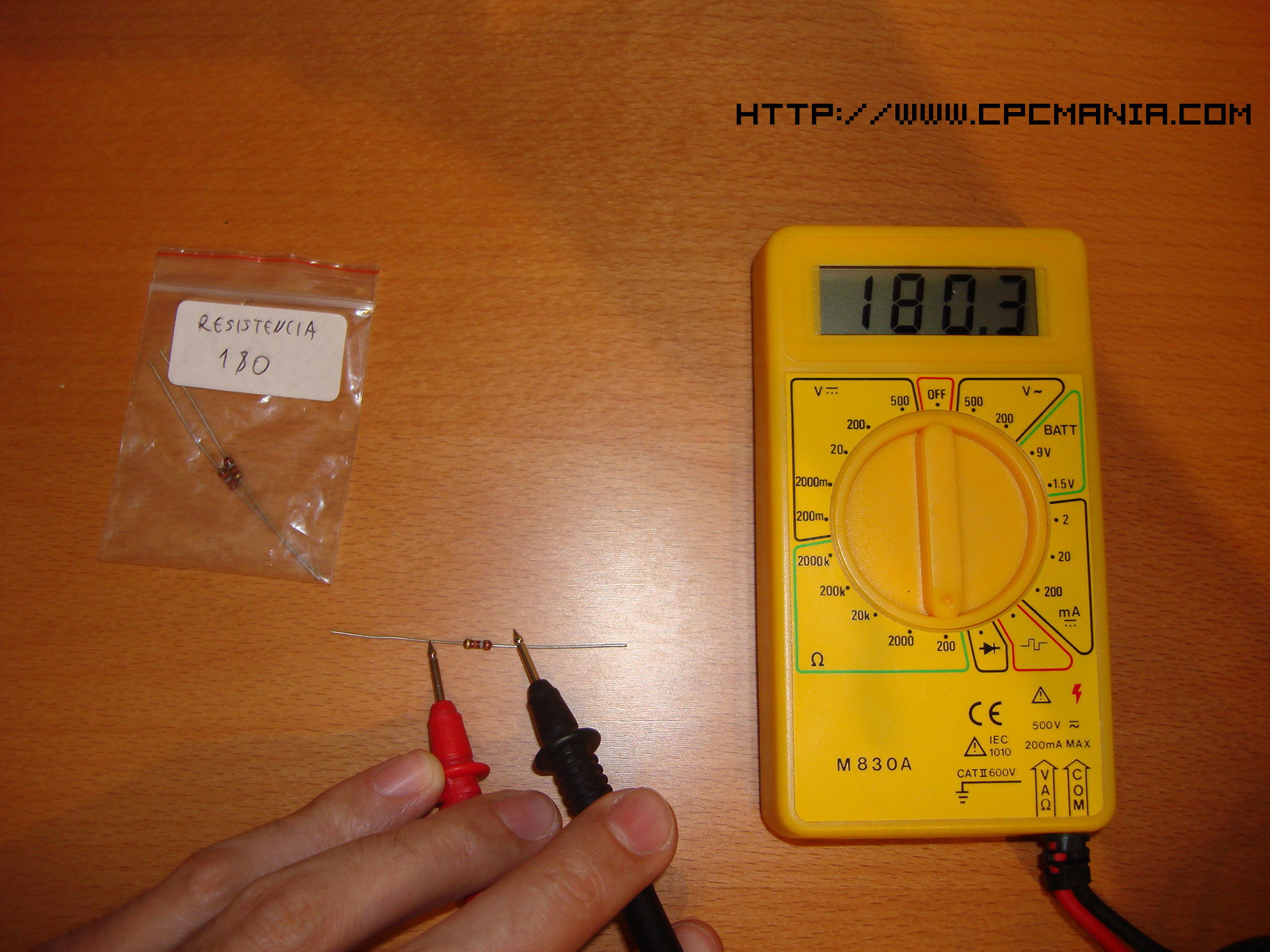
| 180 OHM Resistor |
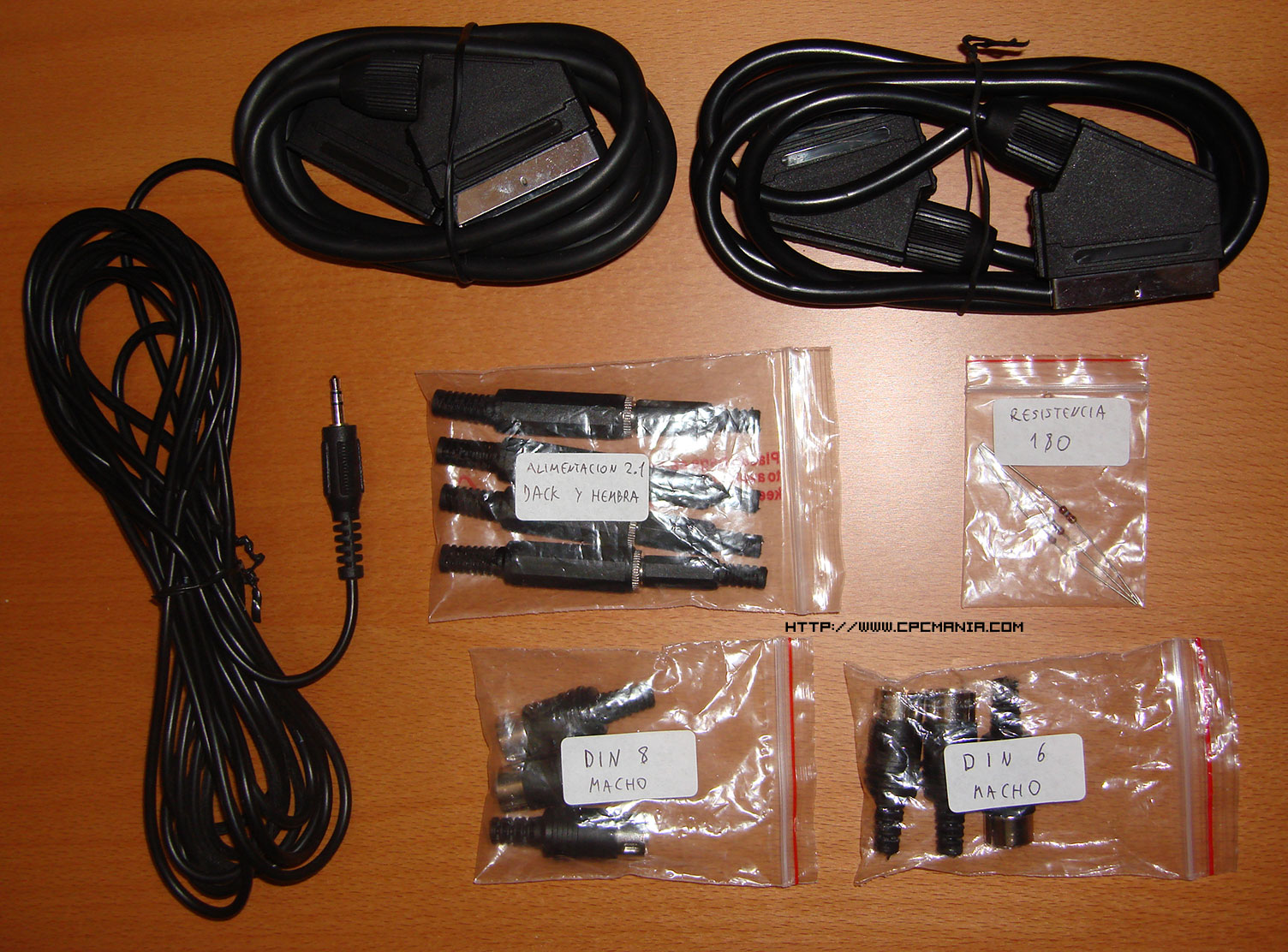
Materials (Click to see bigger)
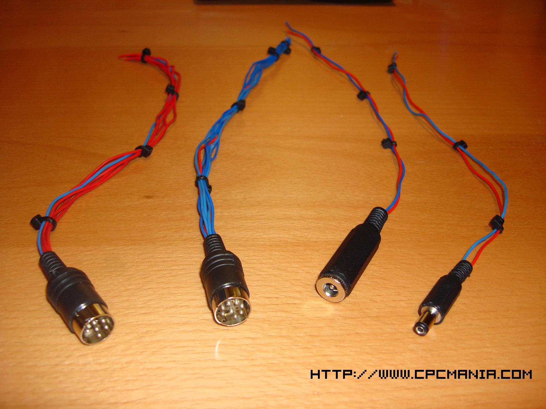
Connectors (Click to see bigger)
| Amstrad CPC 464 Users Manual |
|---|
|
| Amstrad GX4000 Users Instructions |
|---|
|
DIN 6 Connector (Click to see bigger)
DIN 8 Connector (Click to see bigger)
| SCART Pin out |
|---|
Pin 1 Audio output (right) |
Amstrad Sinclair Ocio nº 10 (Click to see bigger)
Amstrad Sinclair Ocio nº 10 (Click to see bigger)
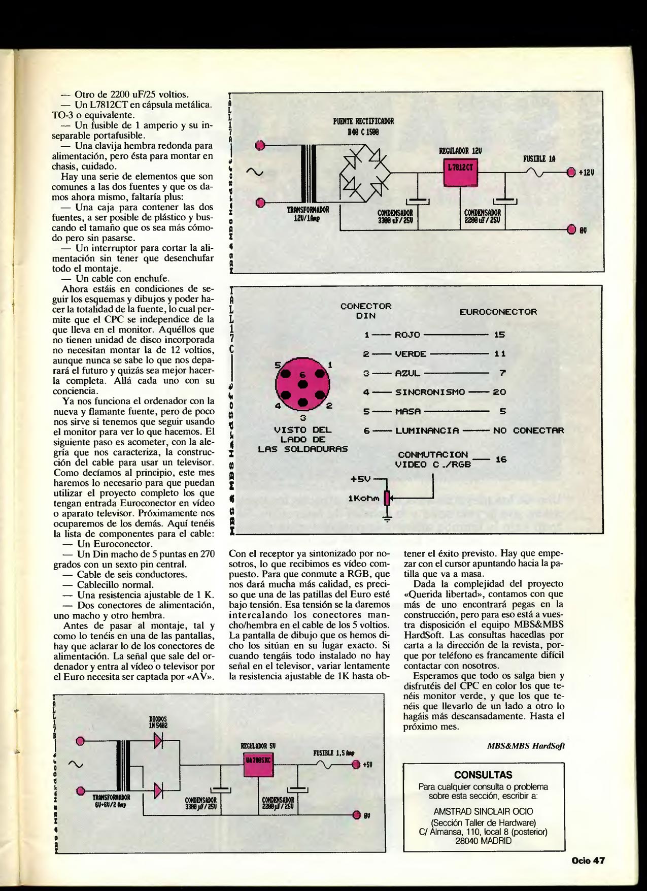
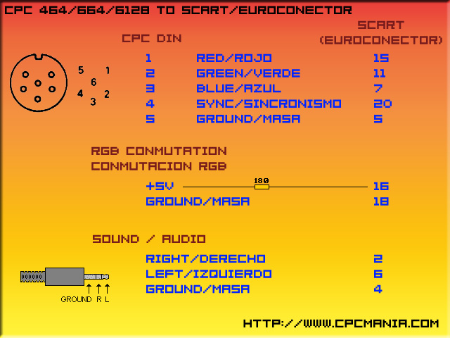
Amstrad CPC to SCART Pinout
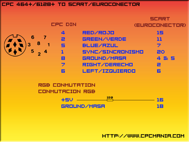
Amstrad CPC+ to SCART Pinout
Hardest solder work (Click to see bigger)
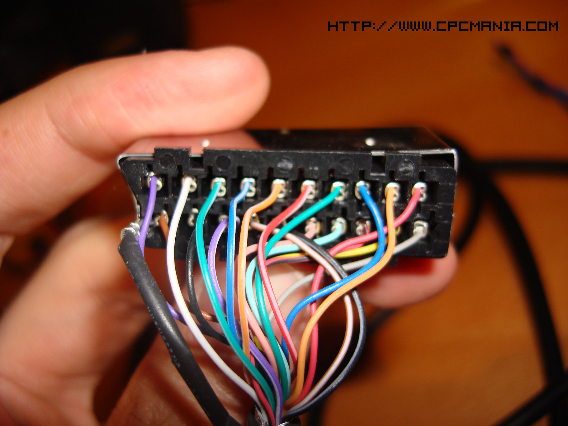
Opening SCART (Click to see bigger)

SCART detail (Click to see bigger)
Testing the resistor (Click to see bigger)
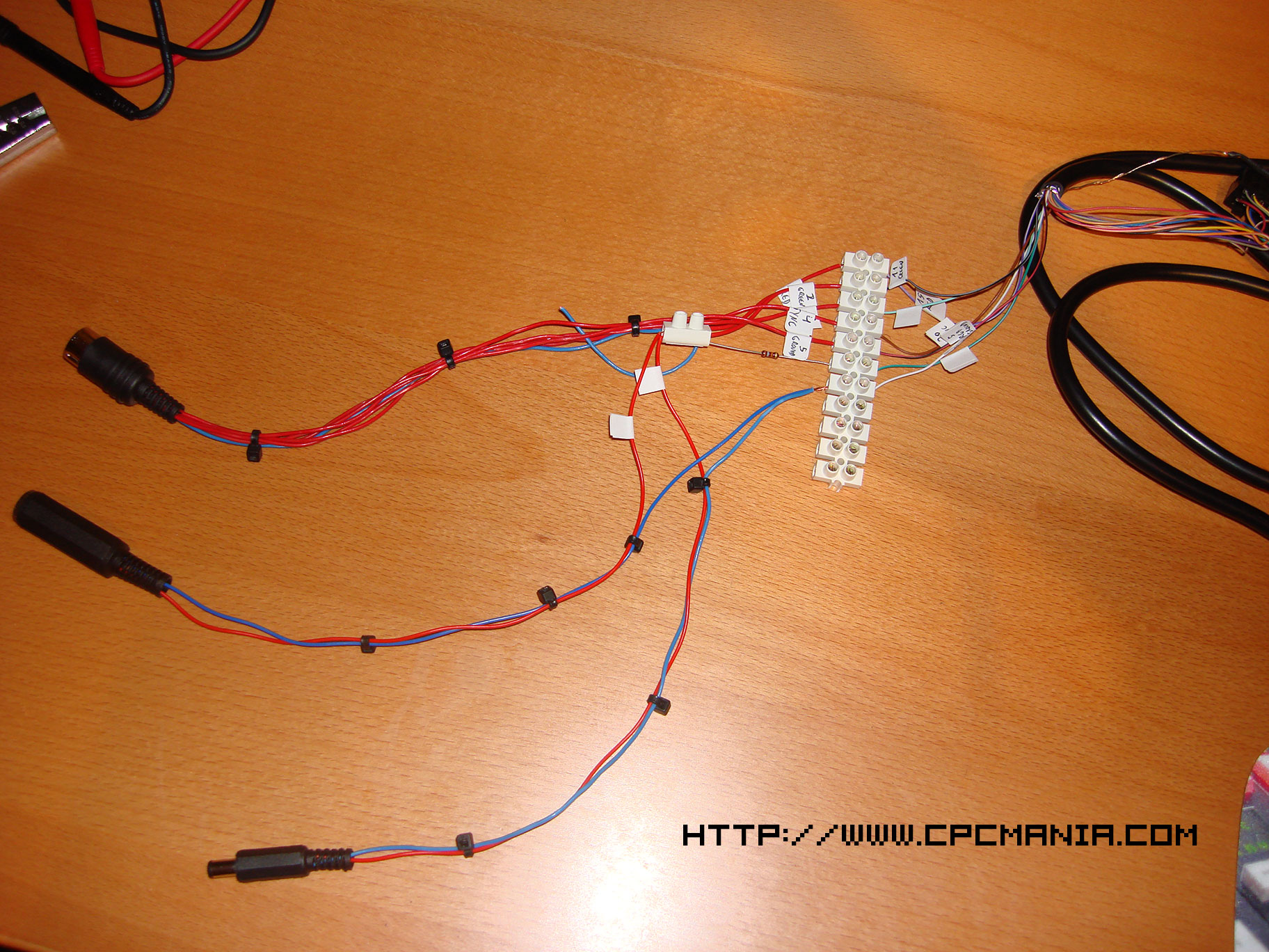
First wiring to test (Click to see bigger)
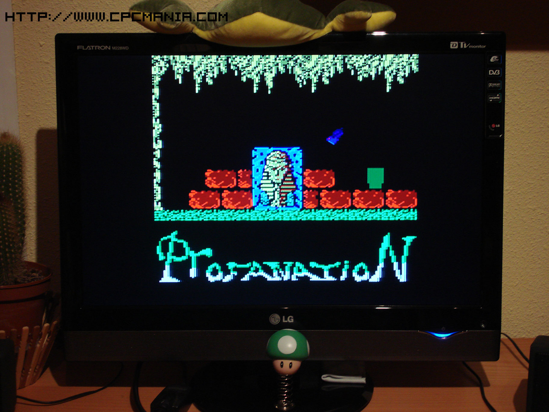
Testing (Click to see bigger)
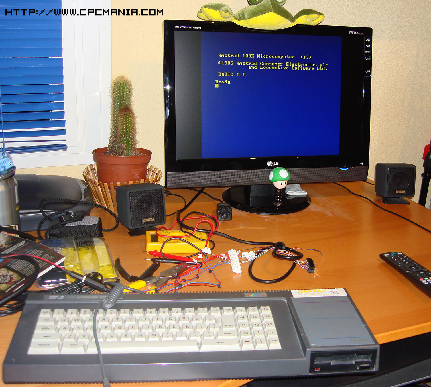
Testing (Click to see bigger)
Testing (Click to see bigger)
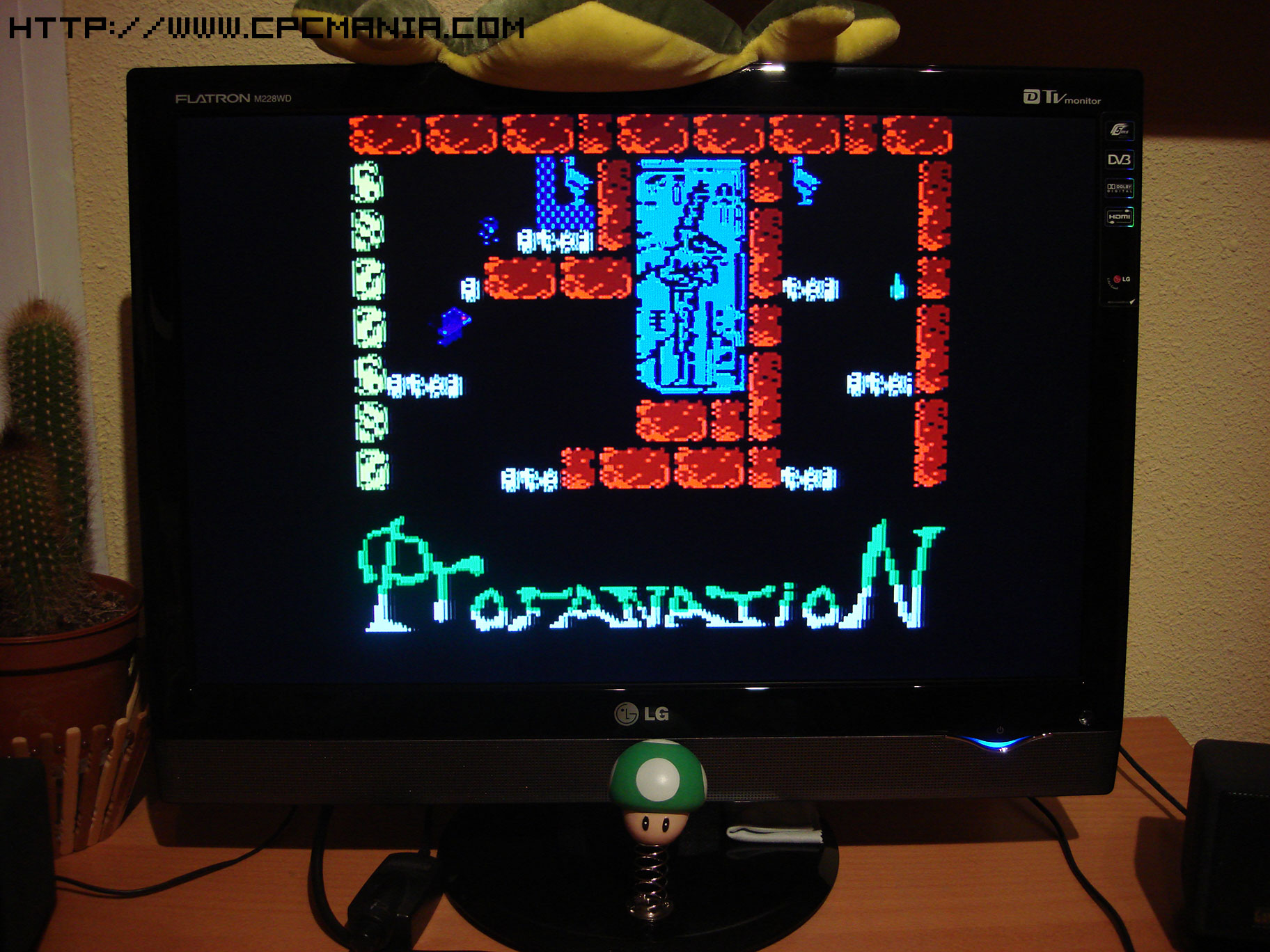
Testing (Click to see bigger)
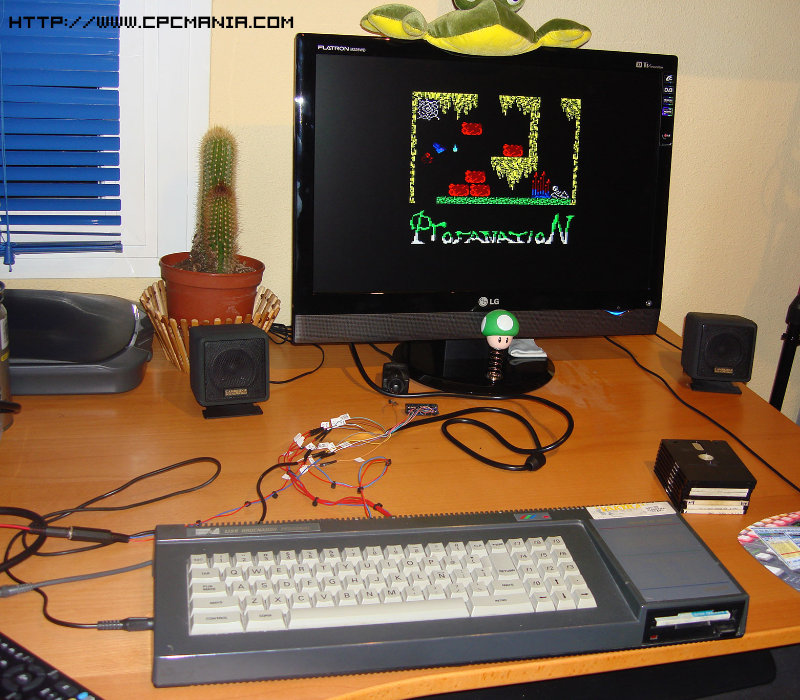
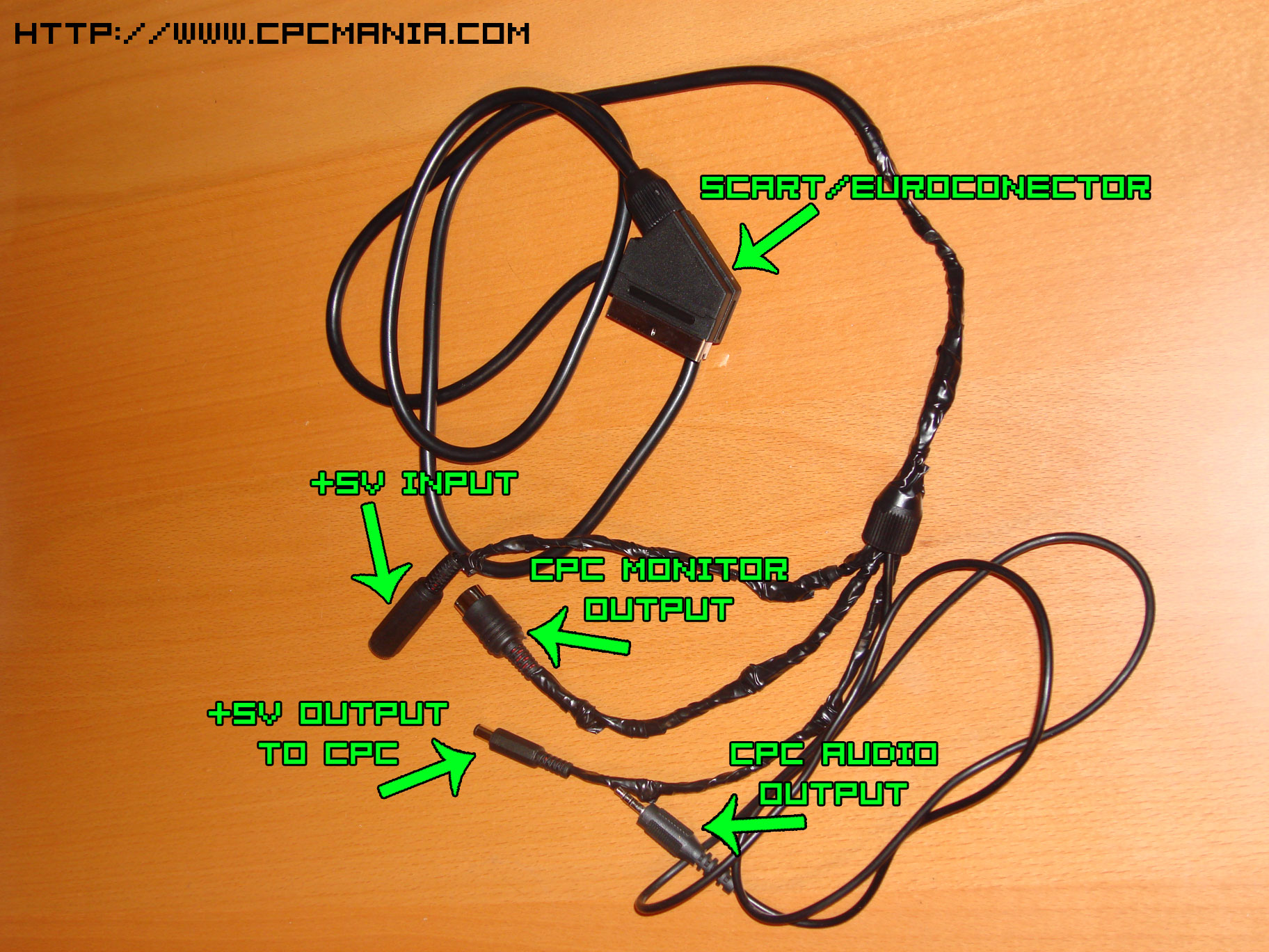
Final result (Click to see bigger)
|
www.CPCMania.com 06 - 07 - 2008 |